|
This paper is available in PDF format.
Direct Gear Design for Spur and Helical Involute Gears
Alexander L. Kapelevich and Roderick E. Kleiss

|
Dr. Alexander L. Kapelevich
is an owner of the consulting
firm AKGears of
Shoreview, MN, and principal
engineer for Kleiss
Gears Inc. of Centerville,
MN. He has more than 20
years of experience in
development of aviation
and commercial gear transmissions
in Russia and the
United States.
Roderick E. Kleiss,
professional engineer, is
owner and president of
Kleiss Gears Inc. His company
engineers and manufactures
high precision,
plastic molded gears using
the direct gear design
approach.
|
This paper presents an alternative method of
analysis and design of spur and helical involute
gears.
Introduction
Modern gear design is generally based on
standard tools. This makes gear design quite simple
(almost like selecting fasteners), economical,
and available for everyone, reducing tooling
expenses and inventory. At the same time, it is
well known that universal standard tools provide
gears with less than optimum performance and -
in some cases - do not allow for finding acceptable
gear solutions. Application specifics, including
low noise and vibration, high density of
power transmission (lighter weight, smaller size)
and others, require gears with nonstandard parameters.
That�s why, for example, aviation gear
transmissions use tool profiles with custom proportions,
such as pressure angle, addendum, and
whole depth. The following considerations make
application of nonstandard gears suitable and
cost-efficient:
- CNC cutting machines and CMM gear inspection
equipment make production of nonstandard
gears as easy as production of standard ones.
- Cost of the custom cutting tool is not much
higher than that of the cutting tool for standard
gears and can be amortized if production quantity
is large enough.
- The custom gear performance advantage makes
a product more competitive and justifies larger
tooling inventory, especially in mass production.
- Gear grinding is adaptable to custom tooth
shapes.
- Metal and plastic gear molding cost largely does
not depend on tooth shape.
This article presents the direct gear design
method, which separates gear geometry definition
from tool selection, to achieve the best possible performance
for a particular product and application.
The direct design approach that is commonly
used for most parts of mechanisms and machines
(for example, cams, linkages, compressor or turbine
blades, etc.) determines their profiles according
to the operating conditions and desired performance.
Ancient engineers used the same
approach for gear design, developing the tooth
shape first and then figuring out a way to get it.
During the technological revolution in the 19th
century, the highly productive gear generating
process was developed. New machine tools
required complicated and expensive tools, hobs
or gear shapers. Common parameters of the cutting
tool (generating rack) were standardized.
This has made modern involute gear design indirect
because the gear tooth profiles depend on a
preselected, usually standard set for parameters of
the generating rack (diametral pitch or module,
pressure angle, addendum and dedendum proportions,
tip radii, etc.) and its location (addendum
modification or x-shift), relative to a standard
pitch diameter of the gear.
Table 1 shows a typical helical gear specification,
where gear parameters and the generating
process (rack and its location) parameters are separated.
The gear as a part does not have a pressure
angle, pitch diameter, diametral pitch or module,
helix angle, addendum or addendum modification.
All these parameters are related to the tool
and generating process. The involute gear has a
number of teeth, base diameter, outside diameter,
helical lead, and base tooth thickness.
The generating rack method of gear design
does not guarantee sufficient gear design. The
minimum number of pinion teeth is limited to
avoid undercut. The addendum modification or xshift
of the generating rack is introduced to balance
bending fatigue stresses and specific sliding
for pinion and gear, and to reduce undercut for
pinions with small numbers of teeth.
Why must tooth profiles be modified or corrected
at the very earliest stages of the gear
design? The modification must occur so early
because the traditional approach is limited by its
own arbitrary selection of generating rack parameters.
The zone depicted (Ref. 1) in x-shift coefficient
coordinates x1 and x2, for a pair of spur
gears z1 = 14, z2 = 28 formed by a standard generating
rack with 20� pressure angle is shown in
Figure 1. The zone shown contains all gear combinations
that can be produced using this particular
generating rack. Its area is limited by the minimum
contact ratio for spur gears εα = 1.0 (isogram
A), the sharp tip of the pinion (isogram B),
and the tip-fillet interference (isograms C and D).
The undercut isograms E and F put additional
limitations on the zone area. Other available gear
combinations exist outside the zone borders, but
in order to realize them, the generating rack parameters
would have to be changed. In other words,
a range of possible gear combinations is limited
by the cutting tool (generating rack) parameters
and the machine tool setup (x-shift).
Direct gear design is the way to obtain all possible
gear combinations by analyzing their properties
without using any of the generating process
parameters. Those parameters can be defined
after the gear design is completely finished.
There were attempts to use the base circle as a
foundation for the involute gear theory, separating
the gear analysis from the gear generating
process. Professor E.B. Vulgakov developed the
so-called theory of generalized parameters for
involute gears (Ref. 2). J.R. Colbourne (Ref. 3)
described an alternative definition of the involute
without using the generating rack. The self-generating
method "gear forms gear" was proposed
for plastic molded gears (Refs. 4 and 5).
According to this method, the top land of the
tooth of one of the gears forms the fillet of the
mating gear and vice versa. At a glance, it looks
similar to a gear shaping or gear rolling process,
but the fact that both gears are described without
the generating rack parameters makes a difference
in their geometry and characteristics.
Involute Tooth Parameters
An involute tooth is formed by two involutes
unwound from the base circle db, outside circle
diameter da and fillet (Ref. 2) (see Fig. 2). Unless
otherwise stated, the following equations are correct
for spur gears and for helical gears in the
transverse section (the section perpendicular to
the axis of the gear). Equation numbers with
alphabetic modifiers are given for use in the
numeric examples listed in Tables 2, 3 and 4.
The profile angle in the intersection point of
the two involutes (tip angle) is
where d∆ is the sharp tip circle diameter.
The profile angle on the outside diameter da is
|
|
αa = acos(db/da)
|
(2)
|
|
|
da = db/cos(αa)
|
(2a)
|
The base pitch is
where z is the number of teeth.
The proportional base tooth thickness is
|
|
mb = Sb/pb = z • inv(ν)/π
|
(4)
|
|
|
inv(ν) = π • mb/z
|
(4a)
|
The proportional top land thickness is
|
|
ma = Sa/pb= z • (inv(ν) – inv(αa))/(π • cos(αa))
|
(5)
|
|
|
cos(αa) + zinv(αa)/(π • ma) = mb/ma
|
(5a)
|
|
|
Sa = pb • ma
|
(5b)
|
|
|
inv(ν) = (π • macos(αa) + zinv(αa))/z
|
(5c)
|
Involute Gear Mesh Parameters
Figure 3 shows the zone of tooth action of the
pinion and the gear in close mesh (backlash is
zero). The close mesh condition is
where
|
|
pw = π • dw1/z1= π • dw2/z2
|
(7)
|
|
|
dw1 = db1/cos(αw), dw2 = db2/cos(αw)
|
(8)
|
|
|
Sw1 = (inv(ν1) – inv(αw)) • db1/cos(αw),
|
(9)
|
|
|
Sw2 = (inv(ν2) – inv(αw)) • db2/cos(αw)
|
|
The operating pressure angle can be found by
substitution of Equation 6 with 7, 8, and 9:
|
|
inv(α w) = (inv(ν1) + u • inv(ν2) – π/z1)/(1 + u)
|
(10)
|
The operating pressure angle is a gear mesh
parameter and it cannot be defined for one separate
gear.
The center distance is
|
|
aw = db1 • (1 + u)/(2 • cos(αw))
|
(11)
|
|
|
db1 = aw • (2 • cos(α w))/(1 + u)
|
(11a)
|
The contact ratio (for spur gears and for helical
gears in the transverse section) is
|
|
εα = z1 • (tan(α a1) + u • tan(α a2)
|
(12)
|
|
|
– (1 + u) • tan(α w))/(2 • π ).
|
|
The profile angle in the bottom contact point
must be larger than or equal to zero to avoid involute
undercut:
for the pinion
|
α p1 = atan((1 + u) • tan(αw) – u • tan(αa2)) ≥ 0,
|
(13)
|
for the gear
|
α p2 = atan((1 + u) • tan(αw)/u – tan(αa1)/u) ≥ 0.
|
(14)
|
The axial contact ratio for helical gears is
where φ (in radians) is the angular shift between
the opposite transverse sections in the helical
mesh (see Fig. 4), and
|
|
φ = (2 • bw) • tan(βb)/db,
|
(16)
|
The fillet profile must provide a gear mesh with
sufficient radial clearance to avoid tip-fillet interference.
The fillet also must provide necessary tooth
bending fatigue resistance and mesh stiffness. The
direct gear design approach allows selection of any
fillet profile (parabola, ellipsis, cubic spline, etc.)
that would best satisfy those conditions. This profile
is not necessarily the trochoid formed by the rack or
shaper generating process.
Tool geometry definition is the next step in
direct gear design. This will depend on the actual
manufacturing method. For plastic and metal gear
molding, gear extrusion, and powder metal gear
processing, the entire gear geometry - including
correction for shrinkage - will be directly applied
to the tool cavity. For cutting tools (hobs, shaper
cutters), the reverse generating approach "gear
forms tool" can be applied. In this case, the tooling
pitch and profile (pressure) angle are selected
to provide the best cutting conditions.
Area of Existence of Involute Gears
Figure 5 shows an area of existence for a pinion
and gear with certain numbers of teeth z1, z2, and
proportional top land thicknesses ma1, ma2 (Ref. 2).
Unlike the zone shown in Figure 1, the area of existence
in Figure 5 contains all possible gear combinations
and is not limited to restrictions imposed by a
generating rack. This area can be shown in proportional
base tooth thicknesses mb1– mb2 coordinates
or other parameters describing the angular distance
between two involute flanks of the pinion and gear
teeth, like αa1– αa2 or ν1– ν2. A sample of the area
of existence for a pair of gears z1 = 14, z2 = 28, ma1
= ma2 = 0.075 is shown in Figure 5. The area of existence
includes a number of isograms reflecting constant
values of different gear parameters, such as
operating pressure angles αw, contact ratios εα, etc.
The area of existence of spur gears (thick line 1) is
limited by isogram εα = 1.0, and undercut isograms
αp1 = 0�, αp2 = 0�. Helical gears can have a transverse
contact ratio less than 1.0 because the axial
contact ratio can provide proper mesh. The area of
existence of helical gears is therefore much greater.
Each point on the area of existence reflects a pair of
gears with dimensionless properties that can fit a particular
application. These properties are pressure
angles, contact ratios, pitting resistance geometry
factor I, specific sliding ratio, etc.

The absolute area of existence includes spur gear
combinations with any values of proportional top
land thicknesses between ma1 = ma2 = 0 to ma1 = mb1
and ma2 = mb2 (phantom line 2). This area is substantially
larger than the area with given values of
proportional top land thicknesses. The zone for a
standard generating rack with 20� pressure angle (as
shown in Fig. 1) is only a fractional part of the available
area of existence as shown by hidden line 3 in
Figure 5. An application of a traditional gear generating
approach for gear pairs outside the zone outlined
by hidden line 3 requires selection of a generating
rack with different parameters. The generation
of some gear combinations (top left and bottom right
corners of the area of existence shown in Fig. 5) will
require different generating racks for the pinion and
for the gear.
Analysis of the area of existence shows how
many gear solutions could be left out of consideration
if a traditional approach based on a predetermined
set of rack dimensions is applied. For example,
spur gears with a high operating pressure angle
(point A on the Figure 5, where the operating pressure
angle αw = 39.5�, contact ratio εα = 1.0), or with
a high contact ratio (point B on the Figure 5, where
contact ratio εα = 2.01, operating pressure angle αw
= 16.7�) could not be produced with standard rack
dimensions. Figures 6a and 6b show these gears.
Figures 6c and 6d are the gears that are achievable
using a standard generating rack that are presented
by points C (αw = 29.6�, εα = 1.0) and D (αw = 15.9�,
εα = 1.64) in Figure 5. Even gears with the same
operating pressure angle (point E in Fig. 5) look
quite different (Fig. 7). The standard designed gear
pair (Fig. 7b) has almost sharp-pointed pinion teeth
and short and stubby gear teeth with excessive top
land tooth thickness. The direct designed gear pair
shown in Figure 7a has a contact ratio εα = 1.47. The
standard designed gear pair has a contact ratio of
only εα = 1.16 in close mesh. In an actual application
with real manufacturing tolerances and operating
conditions, the contact ratio of a standard designed
gear pair could be reduced to an unacceptable level
εα < 1.0.
Synthesis of Gearing: Numerical Examples
There are several ways to define gear parameters
using the direct gear design approach. This
article considers some of them.
Area of existence is known. The initial data for
the synthesis of a pair of gears (z1, z2, ma1, ma2)
could be taken from the area of existence at some
particular point. The coordinates of this point and
center distance aw describe all operating gear
parameters. This calculation procedure and
numerical example are presented in the Table 2.
Area of existence is not known. Typical problems
could be finding the maximum pressure
angle if the transverse contact ratio is chosen or
finding the maximum transverse contact ratio if
the pressure angle is chosen. Both of these cases
require finding the point of area of existence
where isograms aw and εα have the same tangent.
This condition is described (Ref. 2) as:
|
|
cos(αa1)2 • (1 + π • ma1 • sin(αa1)/z1) =
|
(17)
|
|
|
cos(αa2)2 • (1 + π • ma2 • sin(αa2)/z2)
|
|
The fillet between teeth is not involved in gear
mesh operation, but its shape greatly affects gear
performance and durability. In traditional gear
design, the fillet profile is a function of the cutter
shape and the machine tool setup. It typically has
excessive radial clearance resulting in high bending
stresses. Direct gear design does not limit fillet
shape definition. One possibility is to describe
the fillet profile as a trace of the top part of the
mating gear tooth (with corresponding minimum
radial clearance) (Refs. 4 and 5). Application of
finite element analysis allows for forming the fillet
profiles to balance and minimize bending
stresses.
Extreme Parameters of Involute Gears
Point A (tangent point of isograms εα = 1.0 and
αw = max) of the area of existence describes gears
with the maximum achievable operating pressure
angle. There is no such limit for helical gears
because a lack of the transverse contact ratio (εα <
1.0) is compensated by the axial contact ratio εβ.
A sample of a helical gear with high operating
pressure angle (Ref. 6) is shown in Figure 8. In
Figure 5, the point B (intersection point of interference
isograms αp1 = 0� and αp2 = 0�) of the
area of existence describes the gears with the
maximum achievable transverse contact ratio.
Table 5 presents maximum values for operating
pressure angle αwA (Point A of the area of existence)
and transverse contact ratio εαB (Point B of
the area of existence) for gear pairs with different
numbers of teeth and the proportional top land
thicknesses ma1 = ma2 = 0.075. An example of a
spur gear mesh with a high contact ratio is shown
in Figure 9.
Spur gears (contact ratio εα ≥ 1.0) with a minimum
possible number of teeth (Ref. 2) are
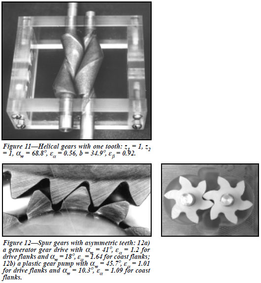
shown in Figure 10. The minimum possible number
of teeth for helical gears is not limited by
transverse contact ratio and could be as few as
one (Ref. 6). An example of a helical gear with the
number of teeth z1 = z2 = 1 is shown in Figure 11.
Involute Gears with Asymmetric Tooth Profile
Opposite flanks (profiles) of the gear tooth are
functionally different for most gears. The workload
on one profile is significantly higher and/or
is applied for longer periods of time than on the
opposite one. The asymmetric tooth shape accommodates
this functional difference.
The design intent of asymmetric teeth is to
improve performance of main contacting profiles
by degrading opposite profiles. These opposite profiles
are unloaded or lightly loaded, and usually
work for a relatively short period. The improved
performance could mean increasing load capacity
or reducing weight, noise, vibration, etc.
Degree of asymmetry and drive profile selection
for these gears depends on the application.
Asymmetric profiles make it possible to manage
tooth stiffness and load sharing while keeping a
desirable pressure angle and contact ratio on the
drive profiles.
Direct design of gears with asymmetric teeth is
considered in detail in other articles (Refs. 7 and
8), covering topics such as analysis and synthesis
of asymmetric gearing, area of existence, and
applications. Examples of gears with asymmetric
tooth profiles are shown in Figure 12. Gears with
asymmetric teeth should be considered for gear
systems that require extreme performance, like
aerospace drives. They are also applicable for
mass production transmissions where the share of
the tooling cost per one gear is relatively insignificant.
The most promising application for asymmetric
profiles is with molded gears and powder
metal gears. Molded gear tooling usually requires
a custom shape, so the asymmetric profile does
not significantly affect cost.
Summary
Direct gear design is an alternative approach to
traditional gear design. It allows analysis of a
wide range of parameters for all possible gear
combinations in order to find the most suitable
solution for a particular application. This optimum
gear solution can exceed the limits of traditional
rack generating methods of gear design.
Direct gear design for asymmetric tooth profiles
opens additional reserves for improvement of
gear drives with unidirectional load cycles that
are typical for many mechanical transmissions.
Acknowledgments
The authors express deep gratitude to Gear Technology
technical editors Robert Errichello of Geartech, located in
Townsend, MT, and Dan Thurman for their help in preparing
this article.
References
1. Groman, M.B. "The Zones of Involute Mesh," Vestnik
Mashinostroeniya, 1962, Issue 12, pp. 12-17 (in Russian).
2. Vulgakov, E.B. Theory of Involute Gears,
Mashinostroenie, Moscow, 1995 (in Russian).
3. Colbourne, J.R. The Geometry of Involute Gears,
Springer-Verlag, New York, 1987.
4. ANSI/AGMA 1006-A97, "Tooth Proportions for Plastic
Gears," Appendix F "Generating Gear Geometry Without
Racks," AGMA, Alexandria, VA, 1997.
5. Kleiss, R.E., A.L. Kapelevich, and N.J. Kleiss. New
Opportunities with Molded Gears, AGMA Fall Technical
Meeting, Detroit, October 3-5, 2001, (01FTM9)
6. Vulgakov, E.B. and A.L. Kapelevicich. "Expanding the
range of involute helical gearing," Vestnik
Mashinostroeniya, 1982, Issue 3, pp. 12-14 (in Russian).
Translated to English, Soviet Engineering Research, Vol. 2,
Issue 3, 1982, pp. 8-9.
7. Kapelevich, A.L. "Geometry and design of involute
spur gears with asymmetric teeth," Mechanism and
Machine Theory, 2000, Issue 35, pp. 117-130.
8. Litvin, F.L., Q. Lian, and A.L. Kapelevich.
"Asymmetric modified gear drives: reduction of noise,
localization of contact, simulation of meshing and stress
analysis," Computer Methods in Applied Mechanics and
Engineering, 2000, Issue 188, pp. 363-390.
|